

What is a Pressure Compensated Flow Control Valve?
A pressure-compensated flow control valve is designed to provide a constant volume flow rate regardless of the pressure drop across it. By contrast, non-pressure-compensated flow control valves have a variable flow rate that changes when the pressure drop fluctuates.
Applications
Pressure-compensated flow control valves are used in a variety of hydraulic applications. They are useful, for example, when it is necessary to maintain a constant speed on a hydraulic cylinder, regardless of the amount of load that the cylinder is under. Because speed is directly proportional to hydraulic fluid flow rate, a hydraulic cylinder’s speed depends on how much fluid is flowing through it.
In a flow control valve without pressure compensation, the flow rate will fluctuate depending on the load on the cylinder. A heavy load on the cylinder will increase the pressure at the valve’s outlet compared to one with a lighter load. By changing the pressure drop across the valve, the flow rate it delivers to the cylinder is altered. Pressure-compensated flow control valves adapt to such pressure changes to maintain a constant flow rate that provides fluid motion at constant speed
Pressure-compensated flow control valves are also useful in maintaining constant rpm of a hydraulic motor independent of load on the motor. Much like the example above, changing loads on the motor will result in a fluctuating pressure drop across the valve ahead of the motor. These fluctuations are compensated for by pressure-compensated flow control valves, which maintain the hydraulic motor’s rpm at a constant level.
It is possible for pressure-compensated flow control valves to compensate pressure fluctuations on either the supply (inlet) or the load (outlet) side of the valve.
Operating principles
Flow control valves that are pressure-compensated normally consist of a variable orifice and a pressure compensator incorporated into one valve body. Flow goes from the supply valve through the inlet and compensated orifice, around the compensated spool, through the variable orifice, and then out the outlet.
By adjusting the pass-through area of the orifice, the desired flow rate is set on the variable orifice. You can make this adjustment either manually using a knob, screw or lever on the valve. Alternatively, by means of electronic signals that are sent to an actuator attached to the variable orifice. Using the pressure compensator, a constant pressure drop is achieved across the variable orifice by modulating the flow of fluid entering the valve. It also provides a constant flow rate across the valve by adjusting the orifice between the inlet flow and the compensator spool.
Variable orifices are made up of valve stems that have a pointed end that can move toward and away from a seat in order to achieve different sizes of openings. Whenever the tip of the stem is in full contact with the seat, the orifice becomes closed, and no fluid can pass. With the stem tip moved away from the seat, the orifice opening becomes larger and more fluid can pass through.
A spool valve with a spring anchors the pressure compensator. Compensation spools consist of a cylindrical barrel with a plunger that slides inside. Plungers have thin and wide sections along their length. As long as the lands and ports are adjacent to each other, they block fluid flow. The wide sections of the barrel are called lands. Spools with narrow, waisted sections allow fluid to pass through them.
By applying a force to the end of the spool attached to the valve housing, a spring keeps the spool attached to it. An additional force is applied to the anchored end of the spool by flowing past the variable orifice in the outlet of the valve. There is a pressure gradient along the line leading from the pressure-compensated flow control valve to the load, such as a hydraulic motor or cylinder.
The fluid that has passed the variable orifice but not yet reached the inlet and compensator is ported to the other end of the spool (the end opposite the end attached to the spring). A force is applied to the spool at this end by the fluid that opposes the force applied by the load pressure and spring pressure. The opposing forces distort the opening of the orifice through which fluid flows from the flow source, modulating the opening of the orifice until the forces at either end of the spool are balanced.
Consequently, fluid flows from the supply, across the compensator spool, and through the variable orifice, while a constant pressure drop across the variable orifice keeps the flow rate constant regardless of changes in pressure between supply and load.
As fluid temperature increases, viscosity increases as well, affecting flow rate. A temperature-sensitive element is incorporated in some pressure-compensated flow control valves, which adapts the position of the compensator when fluid temperatures and viscosity vary. This ensures a constant flow rate regardless of fluid temperature and viscosity. By using a sharp-edged orifice design for the variable orifice, some designs are also able to minimize the variations in flow rate due to changes in viscosity.
In Conclusion
An integral part of a pressure-compensated flow control valve is the pressure compensator. A valve without it would have a variable flow rate when pressure across the valve varies. If more fluid is forced through the valve as a result of a higher pressure drop, the flow rate will be higher; if the pressure drop is lower, the flow rate will be lower.
By automatically adjusting the volume flow rate from the flow supply to the variable orifice, the pressure compensator keeps the internal pressure drop across the variable orifice constant, regardless of the change in pressure drop between the inlet and outlet. With a constant internal pressure drop across the variable orifice, the valve always produces a constant volumetric flow rate regardless of the pressure differences between the valve inlet and outlet. T
his decreases the incoming input process on the inlet port to the lowest operation working pressure for the valve to output accurate flow rates. After regulation, this lowered pressure is applied to the proportional valve orifice, thereby allowing for consistent flow rates even with fluctuating input pressures. So long as the incoming pressure does not drop below the minimum required pressure, accurate proportional flow is maintained to the system.
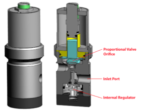
Kelly Pneumatics offers its Pressure Compensated Proportional Valve for projects that require a pressure-compensated flow control valve. There is a mechanical pressure regulator built into the unit, which lowers the incoming input process on the inlet port to the lowest operating working pressure recommended for the valve to output accurate flow rates. By lowering the pressure after regulation, a consistent flow rate can be achieved despite fluctuating input pressures. A proportional flow to the system is maintained so long as the incoming pressure does not drop below the minimum required pressure.